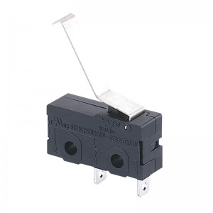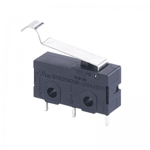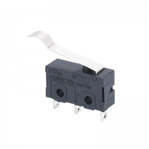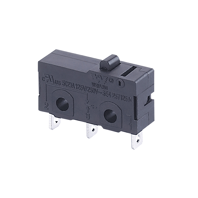
HK-04G-LZ-108
5A 250VAC Mini Micro Switch T125 5E4 for household appliance
|
(The defining characteristics of operation) |
(Operating Parameter) |
(Abbreviation) |
(Units) |
(Value) |
|
|
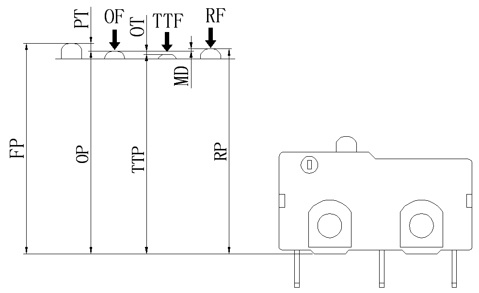
(Free Position) |
FP |
mm |
12.1±0.2 |
| (Operating Position) |
OP |
mm |
11.5±0.5 |
|
| (Releasing Position) |
RP |
mm |
11.7±0.5 |
|
| (Total travel Position) |
TTP |
mm |
10.5±0.3 |
|
| (Operating Force) |
OF |
N |
1.0~3.5 |
|
| (Releasing Force) |
RF |
N |
— |
|
| (Total travel Force) |
TTF |
N |
— |
|
| (Pre Travel) |
PT |
mm |
0.3~1.0 |
|
| (Over Travel) |
OT |
mm |
0.2(Min) |
|
| (Movement Differential) |
MD |
mm |
0.4(Max) |
Switch technical Characteristics
|
(ITEM) |
(technical parameter) |
(Value) |
|
|
1 |
(Electrical Rating) | 5(2)A 250VAC | |
|
2 |
(Contact Resistance) | ≤50mΩ( Initial value) | |
|
3 |
(Insulation Resistance) | ≥100MΩ(500VDC) | |
|
4 |
(Dielectric Voltage) | (between non-connected terminals) | 500V/0.5mA/60S |
|
|
|
(between terminals and the metal frame) | 1500V/0.5mA/60S |
|
5 |
(Electrical Life) | ≥10000 cycles | |
|
6 |
(Mechanical Life) | ≥100000 cycles | |
|
7 |
(Operating Temperature) | -25~125℃ | |
|
8 |
(Operating Frequency) | (electrical):15 cycles
(Mechanical):60 cycles |
|
|
9 |
(Vibration Proof) |
(Vibration Frequency):10~55HZ; (Amplitude):1.5mm; (Three directions):1H |
|
|
10 |
(Solder Ability):(More than 80% of immersed part shall be covered with solder) | (Soldering Temperature):235±5℃
(Immersing Time):2~3S |
|
|
11 |
(Solder Heat Resistance) | (Dip Soldering):260±5℃ 5±1S
(Manual Soldering):300±5℃ 2~3S |
|
|
12 |
(Safety Approvals) |
UL、CSA、VDE、ENEC、CE |
|
|
13 |
(Test Conditions) | (Ambient Temperature):20±5℃
(Relative Humidity):65±5%RH (Air Pressure):86~106KPa |
|
Will the micro switch release the source of interference?
Will the micro switch release the source of interference?
The micro switch is a low-current, low-voltage switching device in electronic equipment and industrial automation electrical equipment. Due to its low operating frequency and relatively small control current, it generally does not produce electromagnetic interference and harmonic interference.
Even if there is weak interference, the isolation transformer used in the control circuit and various filters installed in PLC, touch screen and other components can also reduce the interference to a particularly low level, which is basically negligible.
According to the definition of interference, it can be seen that a signal is interference because it has an adverse effect on the system. Otherwise, it cannot be called interference. It can be known from the factors that cause interference that eliminating any one of the three factors will avoid interference. Anti-jamming technology is the three elements of research and processing.
Devices that generate interference signals are called interference sources, such as transformers, relays, microwave equipment, motors, cordless phones, high-voltage lines, etc., which can generate electromagnetic signals in the air. Of course, lightning, the sun, and cosmic rays are all sources of interference.
Southeast Electronics
The formation of interference includes three elements: interference source, transmission path and receiving carrier. Without any of these three elements, there will be no interference.
The propagation path refers to the propagation path of the interference signal. Electromagnetic signals propagate in a straight line in the air, and penetration propagation is called radiation propagation; the process of electromagnetic signals propagating into equipment through wires is called conduction propagation. The route of transmission is the main reason for the spread and ubiquity of interference.
The control panel or touch screen is a receiving carrier, which means that a certain link of the affected equipment absorbs interference signals and converts them into electrical parameters that affect the system. The receiving carrier cannot perceive the interference signal or weaken the interference signal, so that it is not affected by the interference, and the anti-interference ability is improved. The receiving process of the receiving carrier becomes coupling, and the coupling can be divided into two types: conductive coupling and radiation coupling. Conduction coupling means that electromagnetic energy is coupled to the receiving carrier through metal wires or lumped elements (such as capacitors, transformers, etc.). ) In the form of voltage or current. Radiation coupling means that electromagnetic interference energy is coupled to the receiving carrier in the form of electromagnetic field through space.
In the working environment of the mechatronics system, there are a large number of electromagnetic signals, such as the fluctuation of the power grid, the start and stop of high-voltage equipment, the electromagnetic radiation of high-voltage equipment and switches, etc. When they produce electromagnetic induction and interference shocks in the system, they will often disrupt the normal operation of the system, which may cause system instability and reduce the accuracy of the system.
It can be seen from the above that micro-switches generally do not produce electromagnetic interference and harmonic interference.