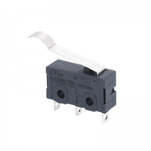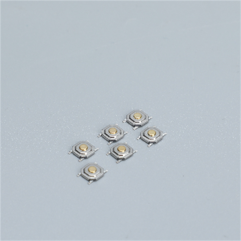
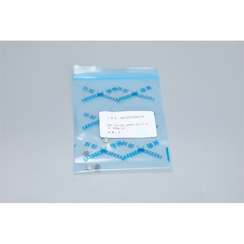
A01-15-C01_4X4X1.5
1.General specification
1.1 Scope
This specification covers the requirements for single key switches which have no key top(TACT SWITCHES:MECHANICAL CONTACT).
1.2 Operating Temperature Range
-20 to +70 ℃ , (normal humidity,normal press.)
1.3 Storage Temperature Range
-25 to +85 ℃ , (normal humidity,normal press.)
1.4Test Conditions
Tests and measurements shall be made in the following standard conditions unless otherwise specified:
Normal temperature (temperature 5 to 35 ℃)
Normal humidity (relative humidity 45 to 85% ) Normal pressure (pressure 860 to 1060 mbars)
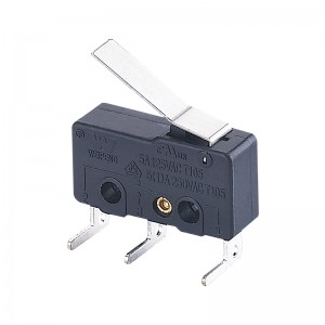
2.TYPE OF ACTUATION
Tactile feedback
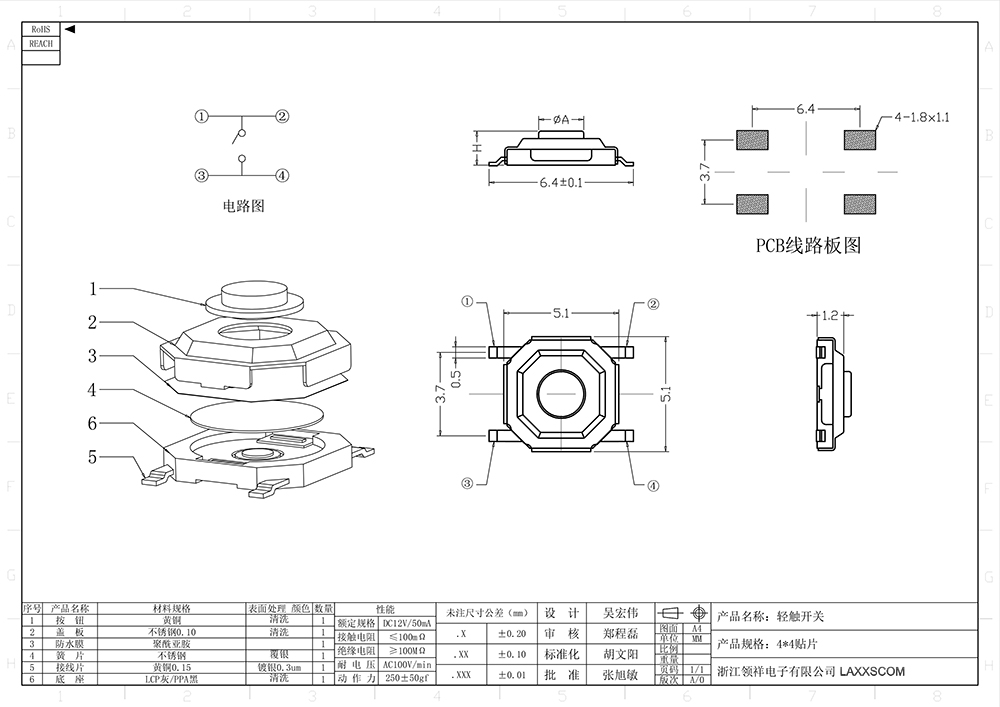
3.CONTACT ARRANGEMENT
1 1 1 poles 1 throws
(Details of contact arrangement are given in the assembly drawings.)
4.MAXIMUM RATINGS DC 12 V 50 mA
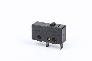
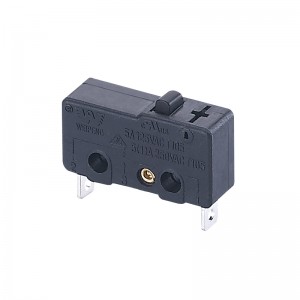
5.Appearance and structure
5.1:Appearance:It should no obvious shrinkin 、upset metal、Scrape、plating path well-distributed and no coming off.
5.2:Size:Making (drawing attached) 2
5.2:Size:Making (drawing attached) 3
6. General specification
6.1Electrical properties
|
Item |
Test Condition | Requirements | |
| 6.1.1 |
Contact Resistance |
1 (kHz).Applying static load twice the actuating force to the center of the stem, measurements shall be made with a 1 kHz small-current contact resistance meter. | 100 mΩ≤ 100 mΩ |
| 6.1.2 | Insulation Resistance |
DC 100 V/ Measurements shall be made following application of DC 100 V potential between terminals and between individual terminals and frame for one minute. |
100 MΩ≥ 100 MΩ |
| 6.1.3 |
Dielectric withstanding voltage |
,AC 250 V (50HZ-60HZ)
AC 250 V (50Hz or 60Hz) shall be applied between terminals and between individual terminals and frame for one minute. |
There shall be no breakdown |
| 6.1.4 | Bounce | ( 3 - 4 ),Lightly striking the center of the stem at a rate encountered in normal use( 3 to 4 operations per sec),Bounce shall be tested when"ON" and "OFF"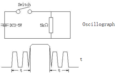 |
10 mS |
6.2 Mechanical properties
|
Item |
Test Condition | Requirements | |
| 6.2.1 | Actuating Force | Place the switch such that the direction of switch operation is vertical and then gradually increase the load applied to the center of the stem,
the maximum load required for the stem to come to a stop shall be measured |
250 ± 50 gf
180 ± 50 gf 100 ± 50 gf |
| 6.2.2 | Travel | Place the switch such that the direction of switch operation is vertical and then apply a static load twice the actuating force to
the center of the stem,the travel distance for the stem to come to a stop shall be measured |
0.15 ± 0.05 mm |
| 6.2.3 | Return Force | , ,The sample switch is installed such that
the direction of switch operation is vertical and,upon depression of the stem in its center the whole travel distance,the force of the stem to return to its free position shall be measured |
250 gf: 80 gf min
180 gf: 60 gf min 100 gf: 40 gf min |
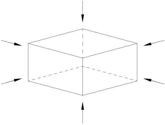
| 6.2.4 | Static Strength | 1KG , 60
Placing the switch such that the direction of switch operation is vertical,a static load of 3 kgf shall be applied in the direction of stem operation for a period of 60 seconds |
There shall be
no sign of damage mechanically and electrically |
6.3 Service Durability
|
Item |
Test Condition | Requirements | |
| 6.3.1 | Operating Life | Measurements shall be made following the test set forth below:
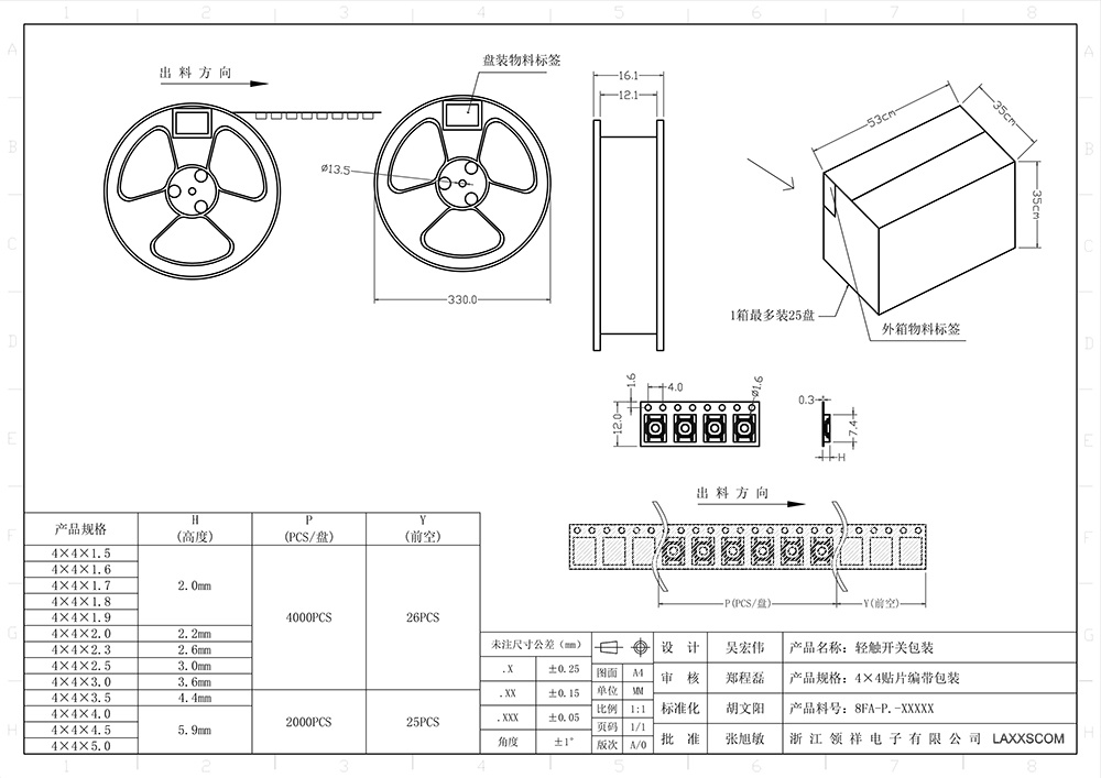
(1) No load condition (2): 60 ~ 120 / Rate of operation: 60 to 120 operations per minute (3): 10 Cycles of operation: Stainless steel 100,000 cycles |
Contact resistance:
300 mΩ Max. Insulation resistance: 100 MΩ Min. Actuating force: ± 30% + 30% or- 30% of initial force Item 6.2.2 |
| 6.3.2 | Moisture Resistance | 1
Following the test set forth below the sample shall be left in normal temperature and humidity conditions for one hour before measurements are made. (1) Temperature: 40 ± 2 ℃ (2) Relative humidity: 90 to 95% (3) Time: 96 hours Water drops shall be removed. |
Contact resistance:
300 mΩ Max. Insulation resistance: 100 MΩ Min Item 6.1.3、6.1.4 Item 6.2.1~6.2.3 |
| 6.3.3 | Low Temperature Resistance | 1
Following the test set forth below the sample shall be left in normal temperature and humidity conditions for one hour before measurements are made (1) Temperature: -20 ± 2 ℃ (2) Time: 96 hours Water drops shall be removed. |
Contact resistance:
300 mΩ Max. Insulation resistance: 100 MΩ Min Item 6.1.3、6.1.4 Item 6.2.1~6.2.3 |
|
Item |
Test Condition | Requirements | |
| 6.3.4 | Heat Resistance | 1Following the test set forth below the sample shall be left in normal temperature and humidity conditions for one hourbefore measurements are made
(1) Temperature: 70 ± 2 ℃ (2) Time: 96 hours |
Contact resistance:
300 mΩ Max. Insulation resistance: 100 MΩ Min Item 6.1.3、6.1.4 Item 6.2.1~6.2.3 |
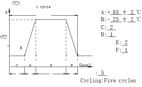
| 6.3.5 | Change of Temperature | 1 Following ten cycles of high temperature test. The Sample shall be Placed in Normal temperature and humidity Conditions for one hour before measurements are made. Duringthis test, water drops shall be removed
|
Contact resistance:
300 mΩ Max. Insulation resistance: 100 MΩ Min Item 6.1.3、6.1.4 Item 6.2.1~6.2.3 |
| 6.3.6 | Salt Spray Test | The salt spray test shall be conducted at the following conditions:(1) Density:( 5 ± 1 )%Nacl() (2) Temperature: 35 ± 2 ℃ (3) Time: 6 hours
24 hours |
No yellowing and rusting of metal parts |
|
Item |
Test Condition | Requirements | |
|
Item 6.1 Item 6.2.1、6.2.2 |
|||
| 6.3.7 | Vibration Resistance | Measurements shall be made following the test | |
| set forth below: | |||
| (1) Range of oscillation: 10 to 55 Hz (2) Amplitude: - 1.5 mm(pk-to-pk: 1.5 mm) (3) Cycle of sweep: 10 - 55 - 10 Hz(in one minute, approx.) | |||
| (4) Mode of sweep: | |||
| (Logarithmically sweep or uniform sweep.) | |||
| (5) Direction of oscillation: 3 ,(Three | |||
| mutually perpendicular directions, including | |||
| the direction of stem travel.) | |||
| (6) 2 . 6 ( 2 hours each,for a total of 6 hours.) | |||
| Measurements shall be made following the test set | |||
| forth below: | |||
| (1) Acceleration: 80 g Cycles of test: 3 , 6 18 ( 3 cycles each in 6 directions, for a total of 18 cycles) | |||
|
6.3.8 |
Impact Shock Resistance |
 |
Item 6.1 Item 6.2.1、6.2.2 |
7. Welding conditions
|
Item |
Recommended conditions | |
|
7.1 |
Hand soldering |
(1):≤ 380 ℃ (2):≤ 3 S (3):≤ 60 WPlease practice according to bellow conditions: (1)Soldering temperature :≤ 380 ℃ (2)Continuous soldering time:≤ 3 S(3)Capacity of soldering iron:≤ 60 W |
| 7.2 | Automatic flow soldering | This product ,type solder according to the following conditions: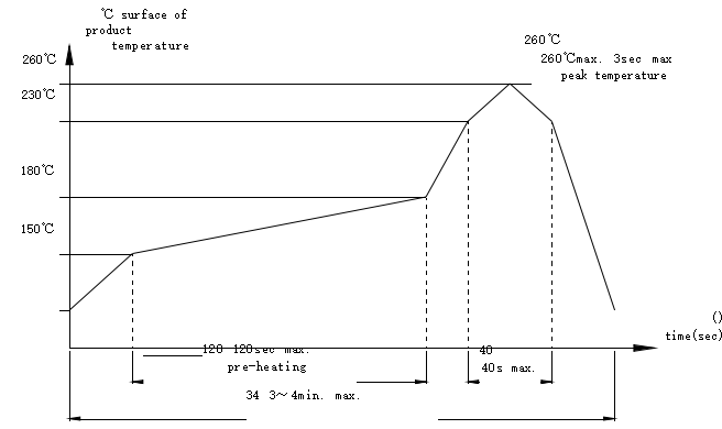 PWB , PWB 、、,PWB ,, 260℃. PWB , PWB 、、,PWB ,, 260℃.
Caution: the condition mentioned above is a temperature on the PWB surface on which parts are mounted. There are cases where PWB temperature greatly differs from switch's surface temperature depending on PWB material,size, thickness,etc. The switch's surface temperature shall not allowed to exceed 260℃ |
8.Other precautions
(1) Following the soldering process, do not try to clean the switch with a solvent or the like.
(2) Safeguard the switch assembly against flux penetration from its topside.
(3) 90 Please have the products keep in close status and the storage time is 90 days guaranty after delivering the goods at most.